-
1 hydraulic fitting
-
2 hydraulic fitting
1) Авиация: арматура гидросистемы2) Техника: гидравлический штуцер -
3 hydraulic fitting
-
4 hydraulic fitting
nHYDRAUL componente para máquina hidráulica m -
5 hydraulic fitting
English-Russian dictionary of terms that are used in computer games > hydraulic fitting
-
6 hydraulic
-
7 fitting
1. n примерка; пригонка, подгонка по фигуре2. n приладка, пригонка3. n спец. фитирование, аппроксимация, подгонка эмпирической кривой4. n тех. установка, сборка, оборудование; монтаж5. n обыкн. приспособления, принадлежности, арматура, деталиfitting — водопроводная арматура, фитинги
pipe fitting — фитинг, трубная арматура
6. n аккорд, набор струн7. a подходящий, годный; надлежащийСинонимический ряд:1. fit (adj.) applicable; appropriate; apt; becoming; befitting; correct; desired; due; felicitous; fit; happy; just; meet; proper; right; rightful; suitable; suited; true2. furnishing (noun) appointment; furnishing3. joint (noun) attachment; bracket; connection; fixture; joint4. agreeing (verb) according; agreeing; check out; comporting; conforming; corresponding; harmonising; rhyming; tallying5. becoming (verb) agreeing with; becoming; befitting; conform to; correspond to; go with; going together; going with; matching; suiting6. going (verb) belonging; dovetailing; fitting; going; setting7. preparing (verb) fixing; getting; making; making up; preparing; readying8. squaring (verb) acclimating; acclimatising; accommodating; adapting; adjusting; conforming; fashioning; reconciling; squaring; tailoring -
8 hydraulic coupling fitting device
English-german engineering dictionary > hydraulic coupling fitting device
-
9 hydraulic connection
fluid connector, fluid fitting, hydraulic connectionгидроразъем, штуцерEnglish-Russian dictionary of program "Mir-Shuttle" > hydraulic connection
-
10 hydraulic test fitting
Техника: диагностический штуцер гидравликиУниверсальный англо-русский словарь > hydraulic test fitting
-
11 fluid fitting
fluid connector, fluid fitting, hydraulic connectionгидроразъем, штуцерEnglish-Russian dictionary of program "Mir-Shuttle" > fluid fitting
-
12 piston
поршень (рис. 3) ; плунжер (рис. 144,7)
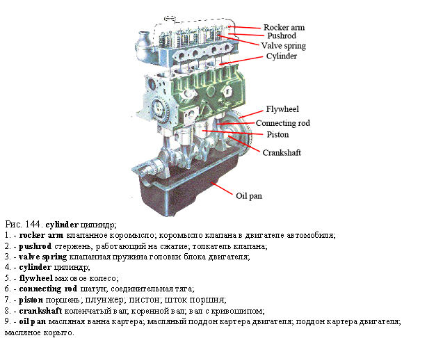 ; пистон; шток поршня; ныряло; клапан; нфт. плавающая (понтонная) крыша резервуара
- piston action
- piston-actuated
- piston actuated clutch
- piston-actuated pressure switch
- piston actuator
- piston-air drill
- piston air valve
- piston alloy
- piston-and-valve arrangement
- piston area
- piston attenuator
- piston barrel
- piston base plate
- piston bearing
- piston cam plate
- piston cooling jet
- piston cooling valve
- piston core
- piston crucible growth
- piston cylinder
- piston-cylinder assembly
- piston damper
- piston drill
- piston-face area
- piston force
- piston face
- piston filler
- piston filling machine
- piston flow
- piston follower
- piston groove
- piston hydropneumatic accumulator
- piston-in-cylinder clearance
- piston knocking
- piston-like
- piston manometer
- piston manufacturing line
- piston meter
- piston mirror
- piston motor
- piston nut
- piston oil ring rails
- piston-operated spool valve
- piston operated valve
- piston pin boss
- piston pin circlip
- piston pin drift
- piston pin end cap
- piston pin knock
- piston pin lock ring
- piston pin locking screw
- piston pin set screw
- piston pin with taper bore
- piston play
- piston ported engine
- piston pressure
- piston pressure gage
- piston pressure gauge
- piston puller
- piston pull scale
- piston pump
- piston pump with cam drive
- piston relief valve
- piston-ring carrier
- piston ring casting
- piston-ring clamp
- piston ring expander
- piston ring gap in bore
- piston ring grinding machine
- piston ring groove
- piston ring joint
- piston ring side clearance
- piston ring slot
- piston-ring spreader
- piston ring sticking
- piston-ring tension
- piston-ring width
- piston rod
- piston rod end
- piston scaler
- piston seal
- piston seizure
- piston separator
- piston shoe
- piston side thrust
- piston skirt
- piston skirt clearance
- piston skirt expander
- piston slap
- piston slipper
- piston speed
- piston sticking
- piston stripping
- piston stroke
- piston-suction sampler
- piston supercharger
- piston support washer
- piston-swept volume
- piston throttle
- piston thrust
- piston-to-head clearance
- piston-to-wall clearance
- piston top
- piston travel
- piston-turning lathe
- piston-turning machine
- piston-type compressor
- piston-type damper
- piston-type drill
- piston-type pump
- piston-type relief device
- piston-type unit
- piston valve
- piston valve cylinder
- piston varnish rating
- piston with slipper
- piston with struts
- piston wrench
- buffer piston
- cast piston
- choke piston
- close-fitting piston
- compensating piston
- contact piston
- contractor piston
- control piston
- dividing piston
- dome-head piston
- double-acting piston
- dual area piston
- flat-crown piston
- forged piston
- free piston
- ground-in piston
- high-pressure piston
- hollow piston
- hammer piston
- intensifier piston
- intermediate piston
- lubricator piston
- magnetic piston
- mud piston
- operating piston
- pent crown piston
- plunger piston
- pot-type piston
- pressure piston
- pump piston
- raised-crown piston
- ramming piston
- reaction piston
- reciprocating piston
- ribbed piston
- rotary piston
- rubber piston
- sand piston
- secondary piston
- seized piston
- seizing of piston rings
- separating piston
- shock absorber piston
- short-circuiting piston
- single-rod piston
- skeleton-skirt piston
- slack piston
- sliding piston
- slipper piston
- slit-skirt piston
- solid piston
- spherical head piston
- split piston
- split skirt piston
- standard piston
- steel piston
- steel-belted piston
- steel-strut piston
- step-head piston
- step piston
- stepped piston
- sticking of piston rings
- stock piston
- strut-type piston
- supported piston
- suspended piston
- T-slot piston
- trunk piston
- trunk-type piston
- two-diameter piston
- two-piece piston
- U-slot piston
- unsuspended piston
- valve piston
- vertical slot piston
- waveguide piston
; пистон; шток поршня; ныряло; клапан; нфт. плавающая (понтонная) крыша резервуара
- piston action
- piston-actuated
- piston actuated clutch
- piston-actuated pressure switch
- piston actuator
- piston-air drill
- piston air valve
- piston alloy
- piston-and-valve arrangement
- piston area
- piston attenuator
- piston barrel
- piston base plate
- piston bearing
- piston cam plate
- piston cooling jet
- piston cooling valve
- piston core
- piston crucible growth
- piston cylinder
- piston-cylinder assembly
- piston damper
- piston drill
- piston-face area
- piston force
- piston face
- piston filler
- piston filling machine
- piston flow
- piston follower
- piston groove
- piston hydropneumatic accumulator
- piston-in-cylinder clearance
- piston knocking
- piston-like
- piston manometer
- piston manufacturing line
- piston meter
- piston mirror
- piston motor
- piston nut
- piston oil ring rails
- piston-operated spool valve
- piston operated valve
- piston pin boss
- piston pin circlip
- piston pin drift
- piston pin end cap
- piston pin knock
- piston pin lock ring
- piston pin locking screw
- piston pin set screw
- piston pin with taper bore
- piston play
- piston ported engine
- piston pressure
- piston pressure gage
- piston pressure gauge
- piston puller
- piston pull scale
- piston pump
- piston pump with cam drive
- piston relief valve
- piston-ring carrier
- piston ring casting
- piston-ring clamp
- piston ring expander
- piston ring gap in bore
- piston ring grinding machine
- piston ring groove
- piston ring joint
- piston ring side clearance
- piston ring slot
- piston-ring spreader
- piston ring sticking
- piston-ring tension
- piston-ring width
- piston rod
- piston rod end
- piston scaler
- piston seal
- piston seizure
- piston separator
- piston shoe
- piston side thrust
- piston skirt
- piston skirt clearance
- piston skirt expander
- piston slap
- piston slipper
- piston speed
- piston sticking
- piston stripping
- piston stroke
- piston-suction sampler
- piston supercharger
- piston support washer
- piston-swept volume
- piston throttle
- piston thrust
- piston-to-head clearance
- piston-to-wall clearance
- piston top
- piston travel
- piston-turning lathe
- piston-turning machine
- piston-type compressor
- piston-type damper
- piston-type drill
- piston-type pump
- piston-type relief device
- piston-type unit
- piston valve
- piston valve cylinder
- piston varnish rating
- piston with slipper
- piston with struts
- piston wrench
- buffer piston
- cast piston
- choke piston
- close-fitting piston
- compensating piston
- contact piston
- contractor piston
- control piston
- dividing piston
- dome-head piston
- double-acting piston
- dual area piston
- flat-crown piston
- forged piston
- free piston
- ground-in piston
- high-pressure piston
- hollow piston
- hammer piston
- intensifier piston
- intermediate piston
- lubricator piston
- magnetic piston
- mud piston
- operating piston
- pent crown piston
- plunger piston
- pot-type piston
- pressure piston
- pump piston
- raised-crown piston
- ramming piston
- reaction piston
- reciprocating piston
- ribbed piston
- rotary piston
- rubber piston
- sand piston
- secondary piston
- seized piston
- seizing of piston rings
- separating piston
- shock absorber piston
- short-circuiting piston
- single-rod piston
- skeleton-skirt piston
- slack piston
- sliding piston
- slipper piston
- slit-skirt piston
- solid piston
- spherical head piston
- split piston
- split skirt piston
- standard piston
- steel piston
- steel-belted piston
- steel-strut piston
- step-head piston
- step piston
- stepped piston
- sticking of piston rings
- stock piston
- strut-type piston
- supported piston
- suspended piston
- T-slot piston
- trunk piston
- trunk-type piston
- two-diameter piston
- two-piece piston
- U-slot piston
- unsuspended piston
- valve piston
- vertical slot piston
- waveguide piston -
13 Brunel, Isambard Kingdom
SUBJECT AREA: Civil engineering, Land transport, Mechanical, pneumatic and hydraulic engineering, Ports and shipping, Public utilities, Railways and locomotives[br]b. 9 April 1806 Portsea, Hampshire, Englandd. 15 September 1859 18 Duke Street, St James's, London, England[br]English civil and mechanical engineer.[br]The son of Marc Isambard Brunel and Sophia Kingdom, he was educated at a private boarding-school in Hove. At the age of 14 he went to the College of Caen and then to the Lycée Henri-Quatre in Paris, after which he was apprenticed to Louis Breguet. In 1822 he returned from France and started working in his father's office, while spending much of his time at the works of Maudslay, Sons \& Field.From 1825 to 1828 he worked under his father on the construction of the latter's Thames Tunnel, occupying the position of Engineer-in-Charge, exhibiting great courage and presence of mind in the emergencies which occurred not infrequently. These culminated in January 1828 in the flooding of the tunnel and work was suspended for seven years. For the next five years the young engineer made abortive attempts to find a suitable outlet for his talents, but to little avail. Eventually, in 1831, his design for a suspension bridge over the River Avon at Clifton Gorge was accepted and he was appointed Engineer. (The bridge was eventually finished five years after Brunel's death, as a memorial to him, the delay being due to inadequate financing.) He next planned and supervised improvements to the Bristol docks. In March 1833 he was appointed Engineer of the Bristol Railway, later called the Great Western Railway. He immediately started to survey the route between London and Bristol that was completed by late August that year. On 5 July 1836 he married Mary Horsley and settled into 18 Duke Street, Westminster, London, where he also had his office. Work on the Bristol Railway started in 1836. The foundation stone of the Clifton Suspension Bridge was laid the same year. Whereas George Stephenson had based his standard railway gauge as 4 ft 8½ in (1.44 m), that or a similar gauge being usual for colliery wagonways in the Newcastle area, Brunel adopted the broader gauge of 7 ft (2.13 m). The first stretch of the line, from Paddington to Maidenhead, was opened to traffic on 4 June 1838, and the whole line from London to Bristol was opened in June 1841. The continuation of the line through to Exeter was completed and opened on 1 May 1844. The normal time for the 194-mile (312 km) run from Paddington to Exeter was 5 hours, at an average speed of 38.8 mph (62.4 km/h) including stops. The Great Western line included the Box Tunnel, the longest tunnel to that date at nearly two miles (3.2 km).Brunel was the engineer of most of the railways in the West Country, in South Wales and much of Southern Ireland. As railway networks developed, the frequent break of gauge became more of a problem and on 9 July 1845 a Royal Commission was appointed to look into it. In spite of comparative tests, run between Paddington-Didcot and Darlington-York, which showed in favour of Brunel's arrangement, the enquiry ruled in favour of the narrow gauge, 274 miles (441 km) of the former having been built against 1,901 miles (3,059 km) of the latter to that date. The Gauge Act of 1846 forbade the building of any further railways in Britain to any gauge other than 4 ft 8 1/2 in (1.44 m).The existence of long and severe gradients on the South Devon Railway led to Brunel's adoption of the atmospheric railway developed by Samuel Clegg and later by the Samuda brothers. In this a pipe of 9 in. (23 cm) or more in diameter was laid between the rails, along the top of which ran a continuous hinged flap of leather backed with iron. At intervals of about 3 miles (4.8 km) were pumping stations to exhaust the pipe. Much trouble was experienced with the flap valve and its lubrication—freezing of the leather in winter, the lubricant being sucked into the pipe or eaten by rats at other times—and the experiment was abandoned at considerable cost.Brunel is to be remembered for his two great West Country tubular bridges, the Chepstow and the Tamar Bridge at Saltash, with the latter opened in May 1859, having two main spans of 465 ft (142 m) and a central pier extending 80 ft (24 m) below high water mark and allowing 100 ft (30 m) of headroom above the same. His timber viaducts throughout Devon and Cornwall became a feature of the landscape. The line was extended ultimately to Penzance.As early as 1835 Brunel had the idea of extending the line westwards across the Atlantic from Bristol to New York by means of a steamship. In 1836 building commenced and the hull left Bristol in July 1837 for fitting out at Wapping. On 31 March 1838 the ship left again for Bristol but the boiler lagging caught fire and Brunel was injured in the subsequent confusion. On 8 April the ship set sail for New York (under steam), its rival, the 703-ton Sirius, having left four days earlier. The 1,340-ton Great Western arrived only a few hours after the Sirius. The hull was of wood, and was copper-sheathed. In 1838 Brunel planned a larger ship, some 3,000 tons, the Great Britain, which was to have an iron hull.The Great Britain was screwdriven and was launched on 19 July 1843,289 ft (88 m) long by 51 ft (15.5 m) at its widest. The ship's first voyage, from Liverpool to New York, began on 26 August 1845. In 1846 it ran aground in Dundrum Bay, County Down, and was later sold for use on the Australian run, on which it sailed no fewer than thirty-two times in twenty-three years, also serving as a troop-ship in the Crimean War. During this war, Brunel designed a 1,000-bed hospital which was shipped out to Renkioi ready for assembly and complete with shower-baths and vapour-baths with printed instructions on how to use them, beds and bedding and water closets with a supply of toilet paper! Brunel's last, largest and most extravagantly conceived ship was the Great Leviathan, eventually named The Great Eastern, which had a double-skinned iron hull, together with both paddles and screw propeller. Brunel designed the ship to carry sufficient coal for the round trip to Australia without refuelling, thus saving the need for and the cost of bunkering, as there were then few bunkering ports throughout the world. The ship's construction was started by John Scott Russell in his yard at Millwall on the Thames, but the building was completed by Brunel due to Russell's bankruptcy in 1856. The hull of the huge vessel was laid down so as to be launched sideways into the river and then to be floated on the tide. Brunel's plan for hydraulic launching gear had been turned down by the directors on the grounds of cost, an economy that proved false in the event. The sideways launch with over 4,000 tons of hydraulic power together with steam winches and floating tugs on the river took over two months, from 3 November 1857 until 13 January 1858. The ship was 680 ft (207 m) long, 83 ft (25 m) beam and 58 ft (18 m) deep; the screw was 24 ft (7.3 m) in diameter and paddles 60 ft (18.3 m) in diameter. Its displacement was 32,000 tons (32,500 tonnes).The strain of overwork and the huge responsibilities that lay on Brunel began to tell. He was diagnosed as suffering from Bright's disease, or nephritis, and spent the winter travelling in the Mediterranean and Egypt, returning to England in May 1859. On 5 September he suffered a stroke which left him partially paralysed, and he died ten days later at his Duke Street home.[br]Further ReadingL.T.C.Rolt, 1957, Isambard Kingdom Brunel, London: Longmans Green. J.Dugan, 1953, The Great Iron Ship, Hamish Hamilton.IMcNBiographical history of technology > Brunel, Isambard Kingdom
-
14 Murray, Matthew
SUBJECT AREA: Land transport, Mechanical, pneumatic and hydraulic engineering, Railways and locomotives, Steam and internal combustion engines[br]b. 1765 near Newcastle upon Tyne, Englandd. 20 February 1826 Holbeck, Leeds, England[br]English mechanical engineer and steam engine, locomotive and machine-tool pioneer.[br]Matthew Murray was apprenticed at the age of 14 to a blacksmith who probably also did millwrighting work. He then worked as a journeyman mechanic at Stockton-on-Tees, where he had experience with machinery for a flax mill at Darlington. Trade in the Stockton area became slack in 1788 and Murray sought work in Leeds, where he was employed by John Marshall, who owned a flax mill at Adel, located about 5 miles (8 km) from Leeds. He soon became Marshall's chief mechanic, and when in 1790 a new mill was built in the Holbeck district of Leeds by Marshall and his partner Benyon, Murray was responsible for the installation of the machinery. At about this time he took out two patents relating to improvements in textile machinery.In 1795 he left Marshall's employment and, in partnership with David Wood (1761– 1820), established a general engineering and millwrighting business at Mill Green, Holbeck. In the following year the firm moved to a larger site at Water Lane, Holbeck, and additional capital was provided by two new partners, James Fenton (1754–1834) and William Lister (1796–1811). Lister was a sleeping partner and the firm was known as Fenton, Murray \& Wood and was organized so that Fenton kept the accounts, Wood was the administrator and took charge of the workshops, while Murray provided the technical expertise. The factory was extended in 1802 by the construction of a fitting shop of circular form, after which the establishment became known as the "Round Foundry".In addition to textile machinery, the firm soon began the manufacture of machine tools and steam-engines. In this field it became a serious rival to Boulton \& Watt, who privately acknowledged Murray's superior craftsmanship, particularly in foundry work, and resorted to some industrial espionage to discover details of his techniques. Murray obtained patents for improvements in steam engines in 1799, 1801 and 1802. These included automatic regulation of draught, a mechanical stoker and his short-D slide valve. The patent of 1801 was successfully opposed by Boulton \& Watt. An important contribution of Murray to the development of the steam engine was the use of a bedplate so that the engine became a compact, self-contained unit instead of separate components built into an en-gine-house.Murray was one of the first, if not the very first, to build machine tools for sale. However, this was not the case with the planing machine, which he is said to have invented to produce flat surfaces for his slide valves. Rather than being patented, this machine was kept secret, although it was apparently in use before 1814.In 1812 Murray was engaged by John Blenkinsop (1783–1831) to build locomotives for his rack railway from Middleton Colliery to Leeds (about 3 1/2 miles or 5.6 km). Murray was responsible for their design and they were fitted with two double-acting cylinders and cranks at right angles, an important step in the development of the steam locomotive. About six of these locomotives were built for the Middleton and other colliery railways and some were in use for over twenty years. Murray also supplied engines for many early steamboats. In addition, he built some hydraulic machinery and in 1814 patented a hydraulic press for baling cloth.Murray's son-in-law, Richard Jackson, later became a partner in the firm, which was then styled Fenton, Murray \& Jackson. The firm went out of business in 1843.[br]Principal Honours and DistinctionsSociety of Arts Gold Medal 1809 (for machine for hackling flax).Further ReadingL.T.C.Rolt, 1962, Great Engineers, London (contains a good short biography).E.Kilburn Scott (ed.), 1928, Matthew Murray, Pioneer Engineer, Leeds (a collection of essays and source material).C.F.Dendy Marshall, 1953, A History of Railway Locomotives Down to the End of theYear 1831, London.L.T.C.Rolt, 1965, Tools for the Job, London; repub. 1986 (provides information on Murray's machine-tool work).Some of Murray's correspondence with Simon Goodrich of the Admiralty has been published in Transactions of the Newcomen Society 3 (1922–3); 6(1925–6); 18(1937– 8); and 32 (1959–60).RTS -
15 Poncelet, Jean Victor
SUBJECT AREA: Mechanical, pneumatic and hydraulic engineering[br]b. 1 July 1788 Metz, Franced. 22 December 1867 Paris, France[br]French mathematician and military and hydraulic engineer.[br]Poncelet studied mathematics at the Ecole Polytechnique in Paris from 1807 to 1810. He joined the Army, gaining admission to the Corps of Engineers. He worked on the fortifications on the Isle of Walcheren in Holland, and in 1812 he found himself on the Russian front, engulfed in the disastrous defeat of the French at Krasnoi. Poncelet was left for dead on the field, but he was found by the Russians and taken to Saratov, where he was imprisoned for two years. He had ample opportunity there to ponder mathematical problems, a mental process from which stemmed his pioneering advances in projective geometry.After his release he returned to this native city of Metz, where he undertook routine military engineering and teaching tasks. These left him time to pursue his mathematical studies in projective geometry. This bore fruit in a series of publications, most notably the first volume of his Traité des propriétés projectives des figures (1822, Paris), the first book to be devoted to the new discipline of projective geometry. With his election to the Académie des Sciences in 1834, Poncelet moved to Paris and devoted much of his time to developing courses in applied mechanics in the Faculty of Science, resulting in a number of books, especially the Introduction à la mécanique industrielle, physique ou expérimentale (1841, Paris: Metz). In 1848 he had attained the rank of general and was made Commandant of the Ecole Polytechnique, a post he held for two years. After his retirement in 1850 he was deeply involved in the industrial machines and tools division at both the Great Exhibition in London in 1851 and the similar exhibition in Paris in 1855.Most of Poncelet's work in applied mechanics and technology was conceived during the period 1825–40. His technological innovations were centred on hydraulic engineering, and in 1826 he invented an inward-flow turbine. At the same time he directed his attention to the vertical undershot water-wheel, with wooden blades set radially and substituted curved metal blades: he used tight-fitting masonry and floors in the wheel pits so that all the water would be swept into the spaces between the blades. In addition, he ensured that the water flowing from the blades fell clear of the wheel and did not run in tail water. This greatly improved the efficiency of the water-wheel.[br]BibliographyH.Tribout, 1936, Un Grand Savant: le général Jean-Victor Poncelet, Paris, pp. 204–20 (the most complete list of his published works).Further ReadingI.Didion, 1870, "Notice sur la vie et les ouvrages du général J.-V.Poncelet", Mémoires de l'Académie de Metz 50:101–59.M.Daumas (ed), 1968, Histoire des techniques, Vol. 3, Paris (briefly describes his technological work).LRD -
16 method
метод; процедура; способ- antithetic variate method - average ordinate method - average range method - binary search method - conjugate directions method - conjugate gradient method - control chart method - conventional milling method - correlation function method - decision function method - differential control method - Feynman diagram method - first approximation method - gradient projection method - iterative method - large sample method - large sieve method - least-squares regression method - less than fully efficient method - linearly implicit method - method of adjoint gradient - method of algebraic addition - method of alternating directions - method of balanced blocks - method of complex numbers - method of confidence intervals - method of conformal mappings - method of conjugate directions - method of conjugate gradients - method of cyclic descent - method of detached coefficients - method of disjunction of cases - method of divided differences - method of electrical images - method of elimination of quantifiers - method of empty ball - method of extreme values - method of false position - method of feasible directions - method of finite differences - method of first approximation - method of first entrance - method of fitting constants - method of fixed points - method of full enumeration - method of generating functions - method of geometric exhaustion - method of indefinite coefficients - method of infinite descent - method of interval bisection - method of least absolute values - method of least distance - method of least likelihood - method of maximum likelihood - method of means and standard deviations - method of medians and extreme values - method of minimal change - method of minimal variance - method of mirror reflections - method of moving frame - method of multiple comparison - method of orthogonal projections - method of paired associates - method of paired comparisons - method of phase integrals - method of projecting cones - method of proportional parts - method of rotating factors - method of semantic tableaux - method of separation of variables - method of simulaneous displacements - method of stationary phase - method of statistical differentials - method of statistical inference - method of steep variations - method of steepest ascent - method of stochastic approximation - method of straightforward iteration - method of successive displacements - method of successive divisions - method of successive elimination - method of transfinite induction - method of unweighted means - method of variable differences - method of variation of parameters - method of weighted residuals - optimum method - parallel tangents method - precision method - random walk method - recursive method - reduced gradient method - reflected wave method - relative method of measurement - sampling method by variables - statistical sampling method - steepest descent method - time average method -
17 dock
1) док; верфь; эллинг || доковать2) ангар3) причал6) помост8) космонавт. стыковаться•-
balance dock
-
basin dock
-
box dock
-
building dock
-
bulk-handling cargo dock
-
dry dock
-
ferry dock
-
fitting-out dock
-
floating dock
-
fueling dock
-
graving dock
-
hydraulic lift dock
-
hydraulic dock
-
oil dock
-
open dock
-
outfitting dock
-
principle dock
-
railway dry dock
-
Rennie dock
-
self-docking floating dock
-
single-walled floating dock
-
slip dock
-
train-ferry dock
-
wet dock -
18 pipe
труба; трубка; трубопровод; бочка (ёмкостью 108 галлонов или 491 л); II транспортировать по трубопроводу; подавать по трубам; снабжать по трубам; перекачивать по трубам; оборудовать системой трубопроводов- pipe-layer - pipe-laying tractor - pipe system - pipe thread - pipe union - adapting pipe - admitting pipe- air pipe- bustle pipe - charge pipe - circulating water pipe - concrete pipe - connecting pipe - curved pipe - elbow pipe - fuel feed pipe - galvanized pipe - hydraulic pipe- jet pipe- lead-lined pipe - lengthening pipe - light pipe - lubricating pipe- oil pipe- pliable pipe - reducing pipe - return pipe - ribbed pipe - right-angle elbow pipe - rising pipe - riveted pipe - seamless pipe - sheet metal pipe - siphon pipe - sleeve pipe - sluice pipe - socket pipe - soil pipe - steam pipe - steel pipe - stub pipe - suction pipe - T-pipe - tail pipe - telescopic pipe - template pipe - terne pipe - three-way pipe - welded pipe - weldless drawn pipe - Y-pipe -
19 piston
1) поршень; плунжер || поршневой; плунжерный2) шток поршня•- balance piston
- box piston
- brake piston
- buffer piston
- close-fitting piston
- control piston
- counter piston
- dash-pot piston
- differential piston
- double-acting piston
- double-rod piston
- dual area piston
- dummy piston
- free piston
- governer piston
- ground-in piston
- hydraulic piston
- load piston
- lubricator piston
- open piston
- single-rod piston
- sliding piston
- solid piston
- trunk pistonEnglish-Russian dictionary of mechanical engineering and automation > piston
-
20 coupling
сцепление; фрикцион; муфта; зубчатая муфта; кулачковая муфта; муфта сцепления; защёлка; собачка; кулак; сопряжение; сочленение (напр. шарнирного устройства); связь (по радио); взаимосвязь; взаимодействие; сцепной прибор; сцепка; цепной замок; стяжка; спаривание; соединение; соединительное звено (напр. цепи); стыковка; связывание; увязка; внедрение; доведение (результатов исследований); II соединительный; связывающий- coupling bar - coupling between oscillations - coupling cable - coupling component - coupling cone - coupling connector - coupling device - coupling edge - coupling end - coupling engagement - coupling error - coupling face - coupling fitting - coupling flange - coupling fork - coupling gasket - coupling half - coupling head - coupling hitch - coupling hook - coupling joint - coupling lever - coupling lifter - coupling link - coupling lock - coupling mechanism - coupling member - coupling nut - coupling of Asiatic profile - coupling of European profile - coupling of pipeline - coupling of pipeline sections - coupling of serie B - coupling pawl - coupling piece - coupling pipe - coupling point - coupling power - coupling ring - coupling rod - coupling screw - coupling screwing-on - coupling shaft - coupling site - coupling size - coupling sleeve - coupling socket - coupling spindle - coupling system - coupling unit - coupling with resilient members - coupling with rubber bushings - adapter coupling - additional coupling - air hose coupling - air-line coupling - ajax flexible coupling - annular coupling - Bibly coupling - capacitive coupling - cascade coupling - cased-muff coupling - clamp shaft coupling - cone coupling - cone-vice coupling - control coupling - cross coupling - cross sliding coupling - curvex coupling - Curvic coupling - cylindrical single-piece body coupling - diaphragm coupling - direct coupling- disk- disengaging coupling - dog coupling - double tapered coupling - double universal coupling - dresser coupling - drum disconnect coupling - eddy current coupling - elastic coupling - electric coupling - electrical coupling - electromagnetic coupling - expanding coupling - expansible coupling - expansion coupling - extension coupling - face tooth coupling - Falk coupling - fast coupling - feedback coupling - female threaded swivel coupling - fire-hose coupling - fixed coupling - fixed Curvic coupling - flange coupling - flanged coupling - flare quick tapered coupling from nickel-plated brass - flexible coupling - flexible block coupling - floating coupling - fluid coupling - fluid coupling adjustable by variable configuration of working space - fluid coupling adjustable by variable filling - fluid coupling with circulation - fluid coupling without circulation - fluid coupling without support - fluid drive coupling - fluted coupling - friction cone coupling - friction coupling - friction clutch coupling - full-floating coupling - funnel coupling - gear coupling - gear tooth-type coupling - gum coupling - hardened coupling - Hirth coupling - Hirth gear coupling - Hirth-ring coupling - Hirth tooth coupling - holdfast coupling - hydraulic coupling - hysteresis coupling - gas male threaded quick coupling - induction coupling - infused emitter coupling - interstage coupling - inverse coupling - jaw coupling - joint coupling - joint-type coupling - keyed coupling - lamination coupling - leather-belt coupling - leather-link coupling - link coupling - load limiting fluid coupling - loading coupling - loose coupling - loose-sliding coupling - Lord coupling - lub'air quick coupling - magnetic coupling - magnetic particle coupling - main coupling - make-and-break coupling - master control coupling - mixed coupling - movable coupling - muff coupling - multidisk coupling - needle coupling - nonlinear coupling - Oldham coupling - Oldum coupling - olive coupling for steel- copper- optimum coupling - overload coupling - parallel two-space fluid coupling - pawl coupling - permanent coupling - permanent shaft coupling - pill-to-pin coupling - pin coupling - pin-and-bushing flexible coupling - pin flexible coupling - pipe coupling - pivot-type coupling - plate coupling - plate-type coupling - pneumatic coupling - powder coupling - pressure coupling - prolac standard coupling with pushbutton for quick disconnection - protecting fluid coupling - pull rod coupling - push-connect air coupling - quick-acting coupling - quick-action coupling - quick-connect coupling - quick olive coupling for compressed air- water- quick-release coupling - rapid coupling - ratchet coupling - reducer coupling - reducing coupling - releasing Curvic coupling - resilient-material coupling - ribbed clamp coupling - rigid coupling - ring coupling - ring compression coupling - rod coupling - rod reducing coupling - roller chain flexible coupling - rope coupling - rotary coupling - rubber annulus coupling - rubber-packed coupling - rubber spider coupling - rubber tire coupling - safety coupling - scoop controlled fluid coupling - screw coupling - screwed coupling - self-aligning coupling - Sellers coupling - semipermanent coupling - semiuniversal Curvic coupling - series two-space fluid coupling - shaft coupling - shear-pin coupling - shift Curvic coupling - single-space fluid coupling - single-support fluid coupling - single universal coupling - sleeve coupling - sleeve-type coupling - slider coupling - sliding coupling - slip coupling - slip joint coupling - solid coupling - spiral jaw coupling - spline coupling - split coupling - split muff coupling - spring coupling - spring-loaded coupling - square-jaw coupling - star coupling - starting-breaking fluid coupling - starting fluid coupling - stationary coupling - straight pipe coupling - stud-retained coupling - sucker-rod coupling - swivel coupling - swivel hose quick release safety coupling - synchronous coupling - teflon-coated tapered threaded male quick release safety coupling - thimble coupling - threaded coupling - threadless coupling - through coupling - tight coupling - toothed coupling - toothed face coupling - tooth ring coupling - tooth-type coupling - torque coupling - trailer coupling - tube coupling - tubing coupling - turned-down coupling - turntable coupling - two-space fluid coupling - two-support fluid coupling - union coupling - universal coupling - universal spindle coupling - variable coupling - vernier coupling - viscous coupling - weak coupling - Westinghouse-Nuttall coupling - working control coupling - zigzag spring coupling
- 1
- 2
См. также в других словарях:
Hydraulic machinery — are machines and tools which use fluid power to do work. Heavy equipment is a common example.In this type of machine, high pressure hydraulic fluid is transmitted throughout the machine to various hydraulic motors and hydraulic cylinders. The… … Wikipedia
banjo fitting — a type of hydraulic fitting, shaped like a banjo, through which a hollow bolt passes, allowing fluid transfer from a hydraulic line to a hydraulic component … Dictionary of automotive terms
JIC fitting — JIC fittings, or SAE J514, or MIL F 18866, are a type of flare fitting having 37 degree flare seating surfaces and are widely used in hydraulic applications. JIC fittings are similar in size and threading to AN fittings. 45 degree flare SAE… … Wikipedia
Cutting ring fitting — before assembly Cutting ring fitting assembled. 1 Body 2 … Wikipedia
American Airlines Flight 191 — For other flights numbered 191, see Flight 191 (disambiguation). American Airlines Flight 191 … Wikipedia
Piping and plumbing fittings — Fittings are used in pipe and plumbing systems to connect straight pipe or tubing sections, to adapt to different sizes or shapes, and to regulate fluid flow, for example. Fittings, especially noncommon types, can be expensive, and require time,… … Wikipedia
T-54/T-55 operators and variants — Infobox Weapon name= T 54/55 caption= US Army recognition poster origin= Soviet Union type= Main battle tank is vehicle= yes is UK= yes service= 1947–present used by= wars= designer= Morozov (T 54), OKB 520 (T 54A and later) design date= 1945… … Wikipedia
Artificial lift — involves the use of artificial means to increase the flow of liquids, such as crude oil or water, to the surface of a production well. Generally this is achieved by a mechanical device inside the well, such as a pump; decreasing the weight of the … Wikipedia
Meillerwagen — Manufacturer Gollnow Son Assembly Germany Class trailer … Wikipedia
Organ — • A musical instrument which consists of one or several sets of pipes, each pipe giving only one tone, and which is blown and played by mechanical means. Catholic Encyclopedia. Kevin Knight. 2006. Organ Organ … Catholic encyclopedia
stage design — Aesthetic composition of a dramatic production as created by lighting, scenery, costumes, and sound. While elements such as painted screens and wheeled platforms were used in the Greek theatre of the 4th century BC, most innovations in stage… … Universalium